Drilling is a machining process that utilizes drill bits to remove material. Today, we will provide a detailed explanation of the principles and characteristics of drilling, as well as the cutting power and resistance, precision and quality of holes in drilling operations.
Principles of Drilling:
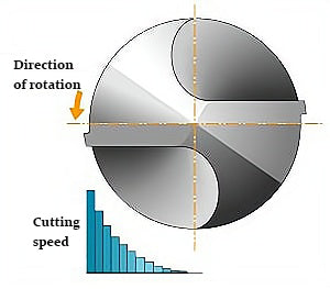
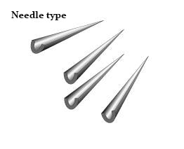
During drilling, the drill bit rotates, allowing two cutting edges to penetrate the workpiece and perform the drilling operation.
Characteristics of the Cutting State in Drilling:
The cutting speed of the drill bit is higher towards the outer periphery and gradually decreases as it approaches the center. At the rotating center, which is the central part of the transverse cutting edge, the cutting speed is zero.
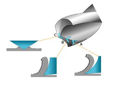
As the drill bit approaches the center, the rake angle decreases gradually. In the C-profile shown, the central part (transverse cutting edge) of the drill bit has a negative rake angle, resulting in a compressive state on the workpiece.
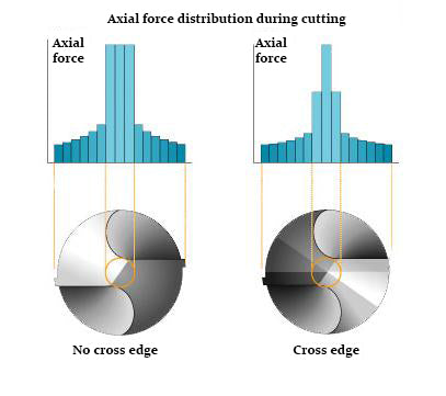
In drilling operations, 50% to 70% of the axial force is consumed in the central part (transverse cutting edge) of the drill bit. By performing transverse cutting edge regrinding, the axial force on the drill bit can be effectively reduced.
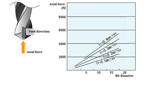
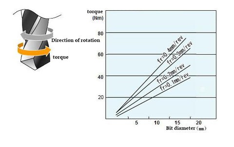
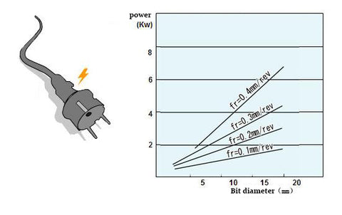
Introduction to Cutting Power and Cutting Resistance in Drilling:
During high-efficiency drilling on machining centers or when using large-diameter drills, it is necessary to confirm the output power of the machine's spindle motor and the cutting power of the drill. Insufficient output power not only prevents processing but can also cause drill bit damage or breakage; this is the main cause of failures. Let's take a look at the following three figures to see how changes in drill diameter and feed affect axial force, torque, and actual cutting power.
Introduction to Chip Shape and Characteristics in Drilling:
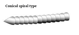
The following figure shows the chip generated during drilling and the state of chip generation. As the rake angle and chip evacuation direction change, the chip is generated at the cutting edge position, which is a complex three-dimensional plastic deformation process. The shape of the chip displays the characteristics of the workpiece material. Conical-spiral, long-pitch, and saw-toothed chips that have an adverse effect on the drill bit can be broken by changing cutting conditions, transverse cutting edge regrinding shape, relief angle, and setting the step feed program.
1.Conical-spiral chip: formed by the fan-shaped chip flowing out of the cutting edge and curling due to the action of the flute. This phenomenon is common in materials with good ductility under low feed conditions. If the chip can be broken after curling for several laps, the chip removal performance is good.
Easy to produce this chip workpiece material: aluminum alloy
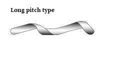
2, long pitch shape: the generated chips are discharged in the state of unrolled, and the discharged chips are easy to wind on the drill.
Easy to produce this chip workpiece material: aluminum
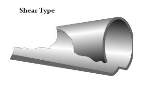
3, shear shape: conical spiral chip is constrained by the machining hole wall, due to the insufficient ductility of the material before the formation of a long pitch shape. Chip removal performance and chip treatment are better.
Easy to produce this kind of chip workpiece material: carbon steel, alloy steel
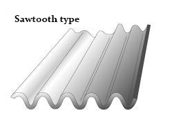
4, zigzag shape: generated chips due to the shape of the groove and material characteristics, bending and folding. Easy to clog in the tank.
Easy to produce this chip workpiece material: stainless steel
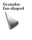
5, granular sector: by the drill groove and machining hole wall constraints and broken chips, in the case of relatively high feed. Chip handling is good.
Easy to produce this chip workpiece material: free cutting steel
6, needle shape: the workpiece material is relatively brittle or small crimp radius, due to vibration fracture of the case of chip. Chip removal performance is better, but easy to plug in the tank.
Easy to produce this chip workpiece material: cast iron
There are many factors that affect the accuracy of hole drilling, including positional accuracy, straightness, enlargement, roundness, and surface roughness of the hole wall.
1.Methods to improve positional accuracy: Positional accuracy refers to the difference between the planned position and the actual position of the drilled hole. If the drill bit has poor cutting performance, it may deviate from the planned position. Using an X-type cross-blade ground drill bit or a short drill bit can effectively suppress this deviation. Additionally, center drills or guide sleeves can be used in previous processes to determine the position.
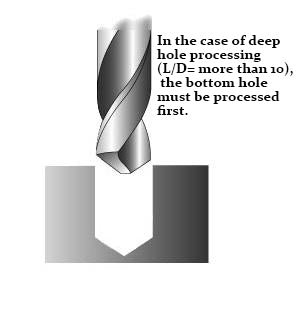
2.Methods to improve straightness of deep holes: The straightness of a hole drilled with a drill bit is represented by its straightness. For deep hole drilling, it is advisable to use a short drill bit for bottom hole drilling, followed by deep hole drilling with a deep hole drill. This can reduce the bending amount of the hole by about 20% to 30% compared to no bottom hole drilling. To improve straightness, it is vital to machine the bottom hole to a depth of L/D = 1 to 3 while ensuring high precision and straightness.
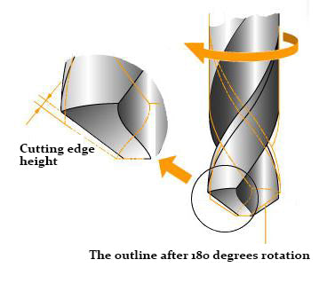
3.Cutting edge height and hole enlargement: The difference between the actual aperture and the drill diameter is called the enlargement amount. Factors that affect the enlargement amount include core thickness, eccentricity of cross blades, and unevenness of the two cutting edges caused by the cutting edge height. Increasing cutting edge height roughly increases the enlargement amount in proportion, so special attention should be paid when installing oscillation and regrinding of the drill bit (the cutting edge height is within 0.02mm). Generally, the enlargement amount of high-speed steel drill bits is about 1% of the drill diameter. The enlargement amount of cemented carbide drill bits is independent of the drill diameter and is roughly 20μm to 40μm.
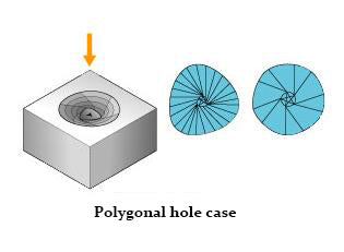
4.Improving roundness: The tip of the drill bit rotates around the ends of the cross blades and undergoes momentary center exchange during repeated machining (walking phenomenon). As a result, the drilled hole may not be perfectly round but polygonal in shape. To achieve holes that are as close to round as possible, effective methods include using drill bits with X-type cross-blade ground edges or reducing the rotational speed of the drill bit and increasing the feed rate.
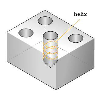
5.Hole wall surface roughness and helix: Factors that affect the roughness of the hole wall include the balance of the cutting edges, the chip removal state, and the adhesion of the blade section. During cutting, if there is walking phenomenon, a spiral-like trace called helix will appear on the hole wall surface, which will deteriorate the surface roughness. The same measures used to improve roundness are important in improving surface roughness of the hole wall, such as changing cutting conditions, reducing cutting edge height, and minimizing the eccentricity of cross blades.